A couple of months into my new job I heard about a makers group spread out across the different offices. After joining a few meetings I was able to get my hands on an extra PCB matching the shape of the company’s iconic badge that was designed and shared before I joined. After seeing what a few other members’ build theirs as I set out to design my own!
Thankfully my parents picked a name short enough so a simple 4 segment display alphanumeric display would be all I need. I had a few extra pieces leftover and started working with those. After a quick search on Adafruit’s blog I found a few tutorials on the Trinket M0 and started up my design.
The Adafruit alphanumeric displays use 14 different segments to make any letter or number under the sun pretty and with the included library it’s a breeze to setup. A couple of minutes and wires later I verified that the display would work perfect. I later added in an extra button that, through programming, I can have to switch between what the display will show.


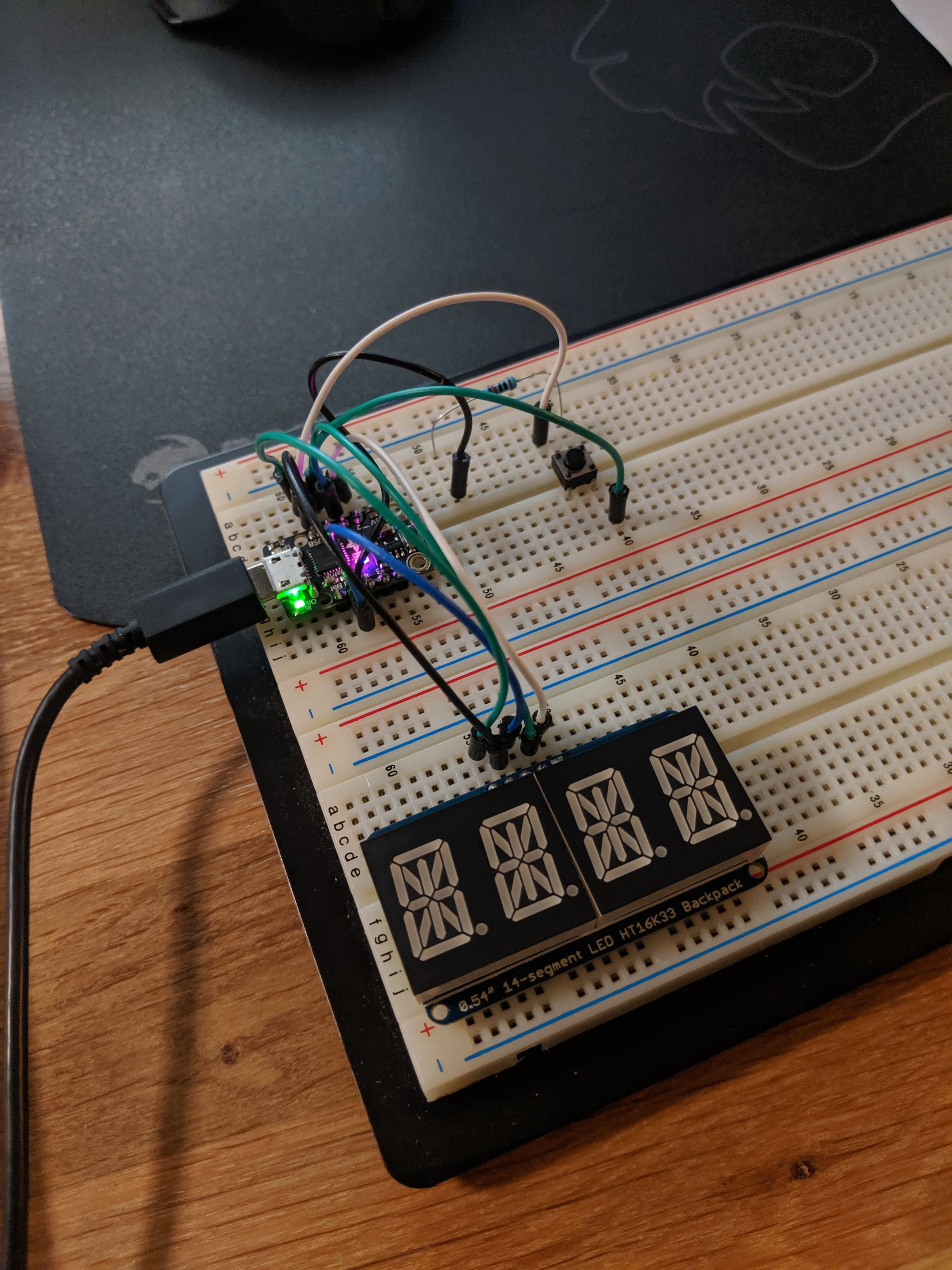
With a general idea at hand I wanted to do some tests on how I would get everything to fit on the board, aside from just the display and control board I’ll need a portable power solution, and power switch as well. The current idea is to have the alphanumeric on the front (duh) shifted to one side with the Trinket on the other. The pins on the alphanumeric are long enough that I should be able to have the backpack for the board on the back of the badge along with power control and a small portable battery. There might need to be some 3d printed parts to hold everything on the back but the idea can change once I have everything dry fit. Running with that plan I placed my order for remaining parts and awaited their arrival!
Once all the parts arrived I begin fitting the known pieces on the board, namely the alphanumeric display and board as that would sandwich on both sides of the board. With that secured in I dry fit the trinket board to figure out what wires and solder points would need to be connected between the two main pieces keeping in mind the main 3rd circuit board of power control and the battery circuit. What followed was a few tense hours of Netflix and solder as I slowly connected up pieces between solder blobs across connections and using silicone insulated wire (MVP of this project) for flexible connections across the board. I tested as often as I could that everything was still properly connected. Adding in the power switch and the power control board together I finally had a completed circuit that mostly copied my breadboard design. I plugged the board up to my computer, uploaded the code and had a working badge!


With a working badge the next steps were to add button controls and a way to attach the badge to my body. The button control I already had mocked on a breadboard so with a few extra wires jumped to the board I had that working cycling through the preset display names. Finally I opened up blender and began mocking up a spider like mesh to attach to the back. The requirements for it are to be just tight enough to fit snug on the back of the badge, to not fall off, and have a wide enough middle connector to allow for a magnetic snap to attach on it so I can put it on my shirt. After a few iterations and quick 3d prints I had a badge holder that wouldn’t snap off! With luck (and the right battery shape) the lipo battery also held in place keeping the 3d print pressured against the badge holding everything together. Another quick 3d design and print for a display stand and My badge was ready for desk display! Using a multimeter I calculated the battery usage at about 6.5 hours with the 400 mAh battery I picked.
Github link to the code: https://github.com/JustAHobby/NameBadgeV1

